


In this article I’ll aim to show you how to design a simple 3D model and then how to create an STL file for 3D printing.
This may sound like a step way down the road for some of you and you may just be happy downloading designs from sights like Thingiverse and printing those. That’s great and there’s absolutely nothing wrong with that. But, at some point haven’t you thought about creating your own design and printing it? Think of the satisfaction you could gain from being able to say, “I made that”.
It’s a bit of a running joke in my family that we’ll see something for sale or on the TV and I’ll say, “I could 3D print that”. Most of the time it is just a joke but there are times when I’ve gone home and tried to either replicate the item or come up with something similar.
I have also been asked on occasion to design and make things for my friends. I’ve duly obliged and they’ve been very happy with the results so far.
But how do you go about designing an object from scratch and then making it so that it can be 3D printed? Well the first stage is to look at 3D design software so let’s start there.
Design Software
You may well know 3D design software as CAD (Computer Aided Design) and there are many different versions out there that you could use. Some are pretty basic but some are fantastic. The only thing is that they tend to be geared to the professional market and as such, carry a hefty price tag.
Not to worry though as the world of 3D printing in the home environment has changed things for the better. With the advent of affordable 3D printers that can be used by the “hobbyist” for want of a better word, software developers have come up with the goods in terms of easy to use and free CAD software.
There are many titles out there but for now, I wanted to focus on three that I would always recommend to new users who want to try their hand at some design.
Tinkercad
This is what I would suggest for use by beginners and that’s what it’s target audience is. It’s also aimed at schools and educators to use as a tool in CAD lessons and to help kick-off an interest in 3D printing amongst pupils. As such, its completely free to use and you don’t even need to download it as all your work is done online.
Blender
Next up is Blender which is a bit of a high step up from Tinkercad and maybe not the best CAD software to dive right into as a beginner. There are a whole host of added features in Blender that you won’t find in Tinkercad and this may be overwhelming for beginners.
Having said that, Blender is great and once you do get the hang of it you’ll be amazed at what you can do. Again, its free but you do need to download it and create a user account.
Fusion 360

This is from the same developers as Tinkercad but takes your design to the next level in terms of detail, quality and appearance.
I’d see Fusion 360 as sitting somewhere between Tinkercad and Blender in terms of what experience you need so its heading towards advancement in your design abilities. The focus from Fusion 360 though would tend to be on objects and engineering rather than character models etc. so this seems more like a traditional CAD program to me.
Like the others, it is free to download but this will only give you the basic version, You can upgrade to the professional version but at a premium of course.
Ok, that’s just a quick look at a few free design programs but now lets get down to the process of making your own design and how to create an STL file for 3D printing.
What’s an STL File?
You may be reading this and asking that very same question so I’ll clear that up now by telling you that STL stands for “Standard Tessellation Language” and is the most commonly used file type in the world of 3D printing. I’m aiming to show you how to create a design that you can 3D print but it won’t be possible without converting the file to an STL file for 3D printing. We’ll come back to that though at the end of this article and after I’ve shown you the design process.
The Design Process
So, I’ve shown you briefly three of the design programs that are commonly used and these are all ones that I personally use. However, I did say that I usually suggest Tinkercad as a great starter program for beginners so let’s practice what I preach and show you how to create a design in Tinkercad.
The first thing you’ll obviously need to do is get into the software itself. This is pretty straightforward so just go to Tinkercad.com and follow the sign up steps to create an account. You’ll need to sign up as a personal user unless you’re in full time education or a professional educator yourself. I have the personal user account so I can start creating from there.
Once you’ve created your account and profile (don’t worry, you won’t get any spam emails or be asked to pay for upgrades etc.) you can start tinkering.
Firstly, go to the “dashboard” where you’ll see your profile picture if you’ve added one and in the middle of the screen a button that says “+create” which I’ve put an orange ring around on Image 1 below. Click on this, choose “3D Design” from the dropdown and you’ll be taken to the main design area of Tinkercad as shown in Image 2 below.
Image 1
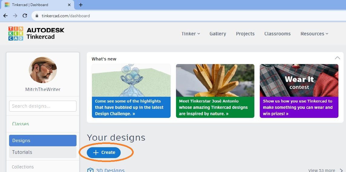
Image 2
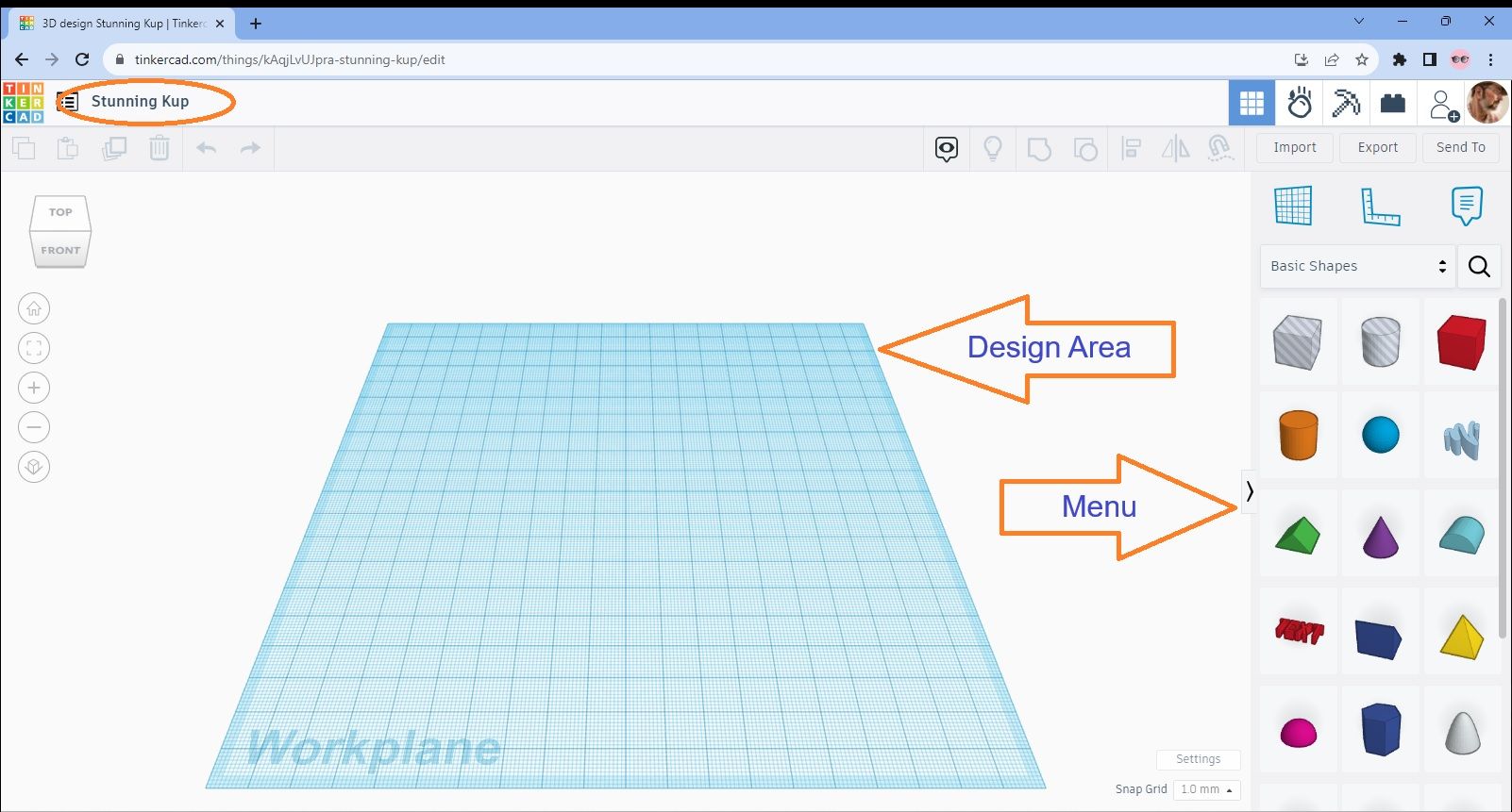
You’ll notice that I’ve pointed out the Design Area and the Menu on the screen. You may also notice that I’ve ringed the title of the model in the top left corner. This is autogenerated by Tinkercad and is just a random set of two or three words. That’s OK when you remember to change it before saving but not if you forget and try to find it later on!
OK, so now we’ve got this far it’s time to start our design. You may have noticed when you were on the dashboard that there was a tutorials button. These are great and well worth following as a starter. I’ve found though that I’ve learnt far more about Tinkercad just by using it and trying things out. Its all a case of how you learn as an individual and my approach is learning by doing.
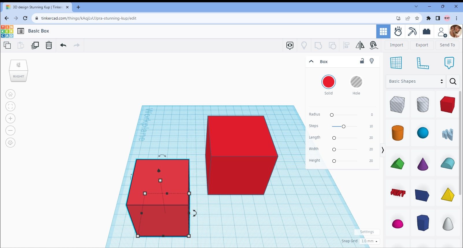
Next, we need to decide what we’re going to design. Now, I’m not going to make this too complicated so please don’t expect a scale model of the Trevi Fountain on our first attempt! However, I think it’s worth designing something that’s worth printing rather than just show you how to create a box. But first, I will show you how to create a small box!
So, go to the right hand menu and select the red box as shown in Image 3. Then hold this and drag it to the centre of the design area as per Image 4.
Image 3
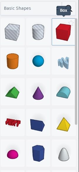
Image 4
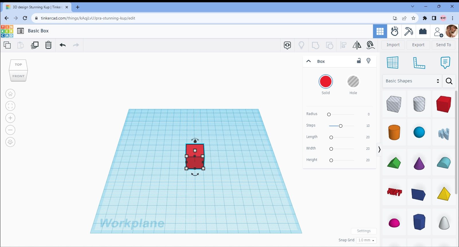
Our box at this stage is pretty small at only 20x20x20mm so lets expand it and make it a bit larger. There are two ways you can do this. When you placed the box in the design area, you will have noticed another menu appear and some small squares around the front face of the box. These squares are the dimension of the box faces so click on the bottom right square and it will bring up two dimensions, one for the width and one for the length.
At the moment these are both 20mm as we’ve established. We want to change these to 50mm each so firstly, click on the 20 at the right hand side of the box. This will highlight it in blue and then you can just type in “50” and hit return. Follow the same process for the front width and your box will now be 50x50x20mm. You can see this in Images 5 and 6 below.
Image 5
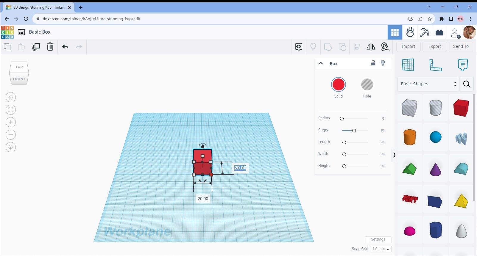
Image 6
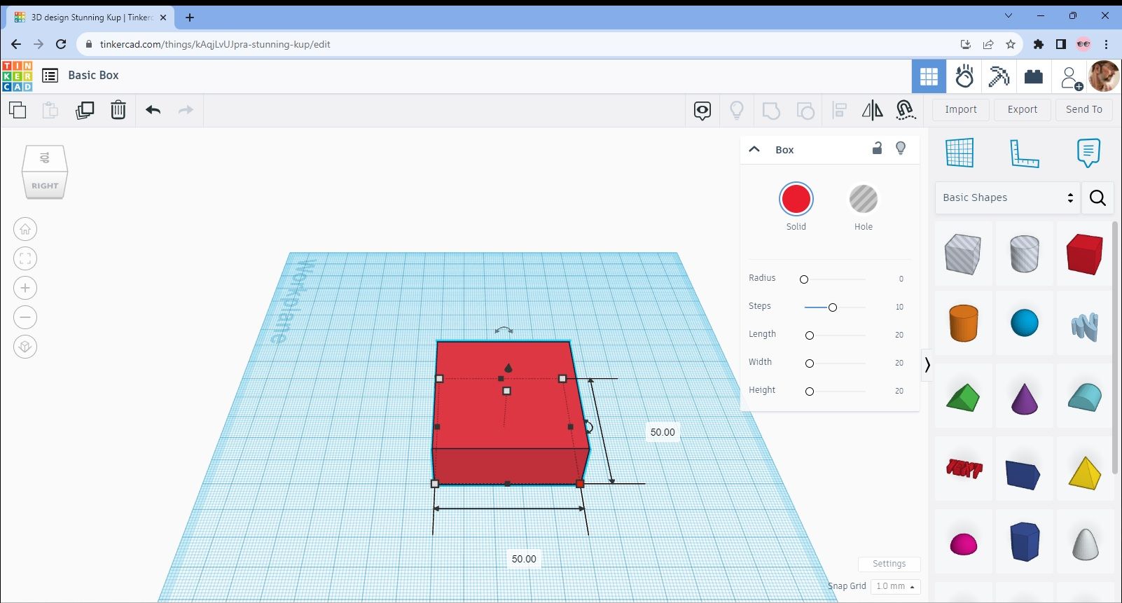
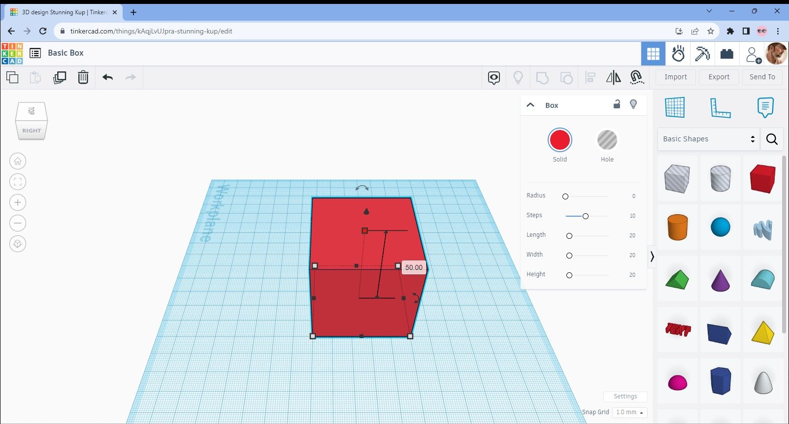
We still want a cube shape so click on the fifth square which forms the top point of a triangle made by the upper white squares. Click on this and follow the same process as before. You should now have a 50x50x50mm box shape as in Image 7.
Image 7
I mentioned that there was another way to change these measurements and you’ll see that in the new menu on the right that appeared when you added the box. Just type in “50” over the 20s that are there for each side and the shape will then change automatically.
Now, that is a much easier way of doing things so why did I go through the other method I hear you ask, Well I wanted to give you both options as you may be like me and like to visualize the figure by working directly on it. It might be a bit more involved but that’s just how I roll.
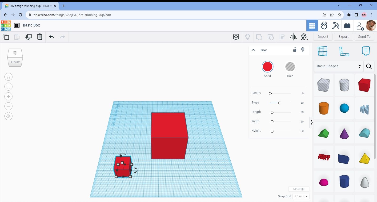
Right, back to the box. At present it isn’t really a box but just a cube. We therefore need to create a hollow which will form the interior of the box. For ease, let’s say that the walls of our box are going to be 5mm thick on all sides with an open top. We therefore need to first create another box which will fit these criteria.
The easiest way to create another box is to just do what you did before but place it in a different part of the design area. Take a look at Image 8 to see what I mean.
Image 8
We now need to make this the size of the void that we want to create for the interior of the box. So, If each wall is to be 5mm thick but the top is open, by my calculations box 2 needs to be 40x40x45mm. Therefore change the dimensions by whatever method you prefer and you’ll then have these two boxes as in Image 9.
Image 9
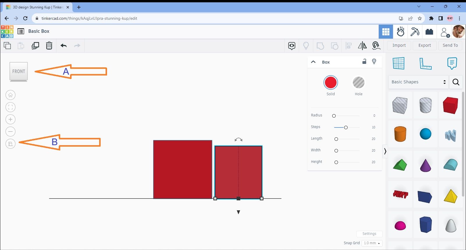
Now we need to move box 2 so that its in position where we want the void to be in box 1. At the moment, the screen is in a 3D mode and showing the front elevation. It’s easier to see where you’re moving objects to if you change the view to the left side in the first instance. You can do this by clicking on the image of the box on the top left hand side of the screen (arrow A) and simply click on the highlighted side you want to see. Then click on the other image of a box at the bottom of the left hand menu to change the perspective (arrow B). Have a look at Image 10 and this should now be your view (apart from my arrows of course).
Image 10
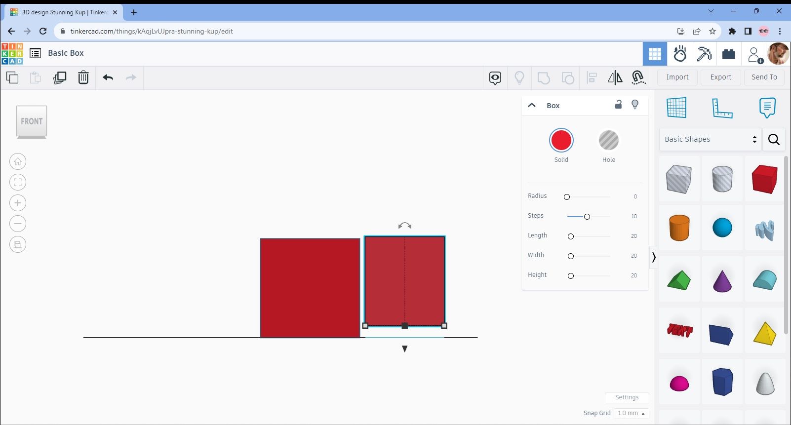
You’ll see of course that box 2 is smaller than box 1. So, we need to raise it so that it’s just above the top of box 1 in order for us to be able to see it in the next stage. Do this by clicking on the black arrow underneath box 2 and then moving it with the mouse. Raise it up 6mm at this stage so its then just above the top face of box 1 as in Image 11.
Image 11
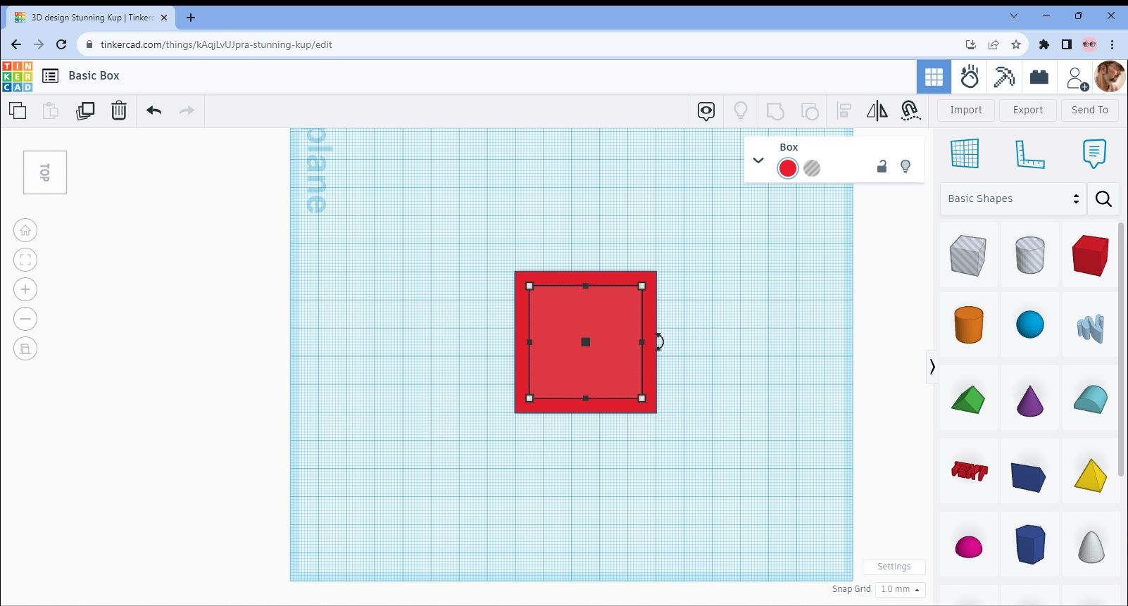
The next thing we need to do is move box 2 into box 1 so the easiest way I find to do this is by using the arrow keys on your keyboard. However, you’ll need to change the view again to the top down. Then gradually and carefully move box 2 with the keys until it sits in the centre of box 1 as shown in image 13.
Image 12
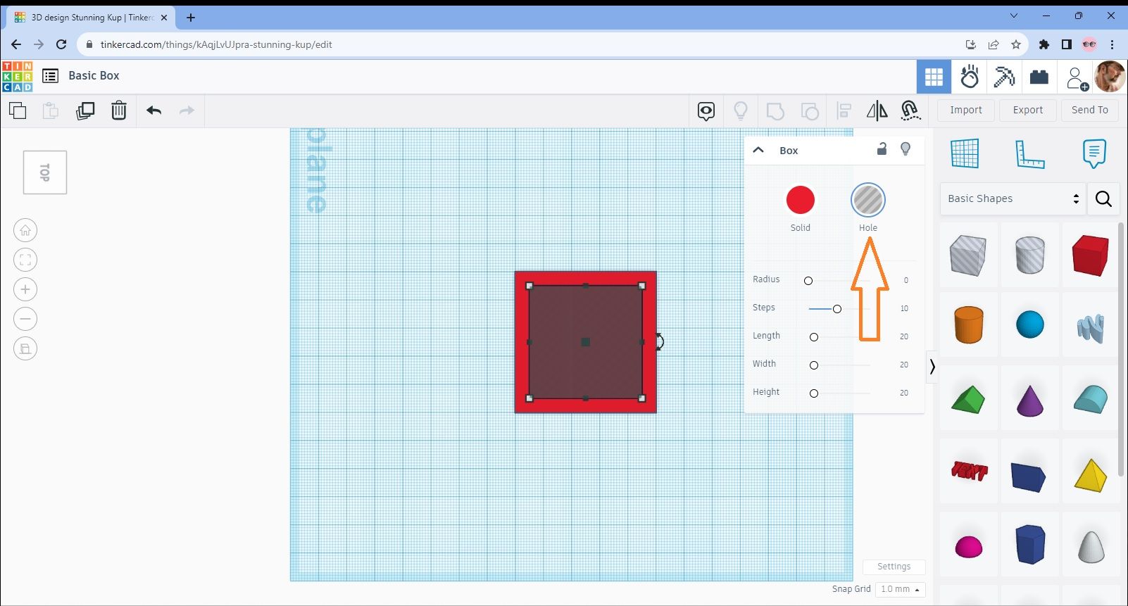
What we need to do now is convert box 2 from a solid object to a hole. This is really simple and just requires selecting box 2 and then licking on the “hole” button that you’ll see on the dropdown menu to the right (arrowed). You should then have this view as in Image 13.
Image 13
Go back to the side on view again and move box 2 down by just 1mm. I won’t show you the view of this as it’s basically just the side of box 1.
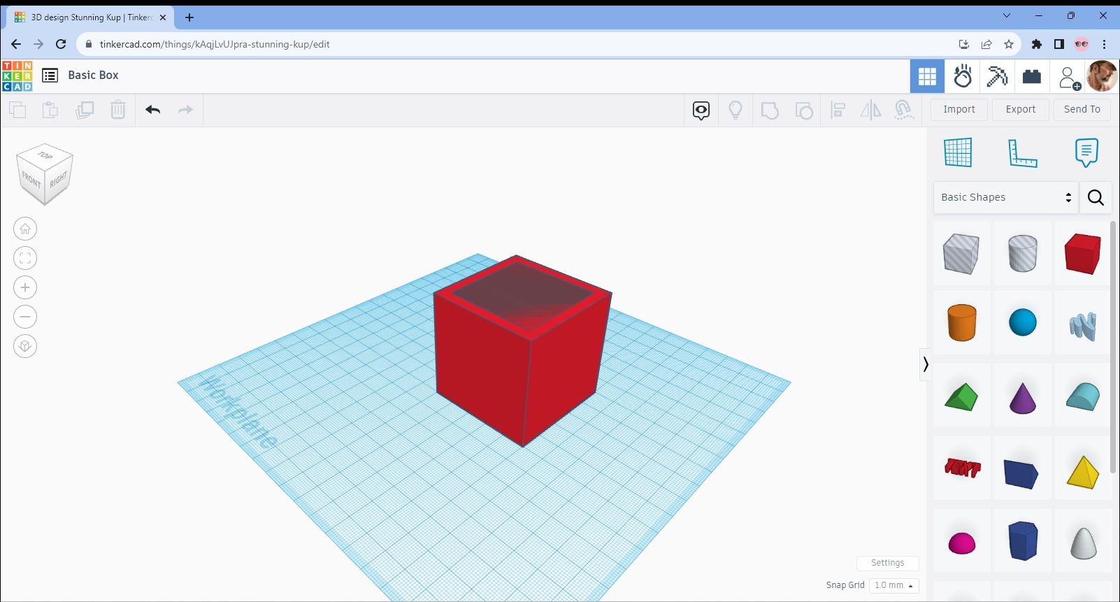
You should now have created a 50x50x50mm box with 5mm thick walls and an open top. Have a look at Image 14 and hopefully your design will look very similar to this.
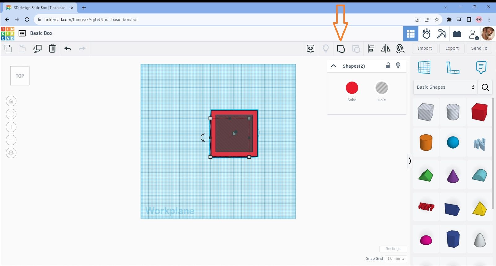
The last thing we need to do now is to group the 2 boxes together so that they form one object. To do this, change back to a top down view and right click on your mouse and drag it over the boxes so that both are selected. You’ll notice that one of the icons in the tool bar has darkened and this is the “group” button as indicated in Image 15 and shown by my arrow.
Image 15
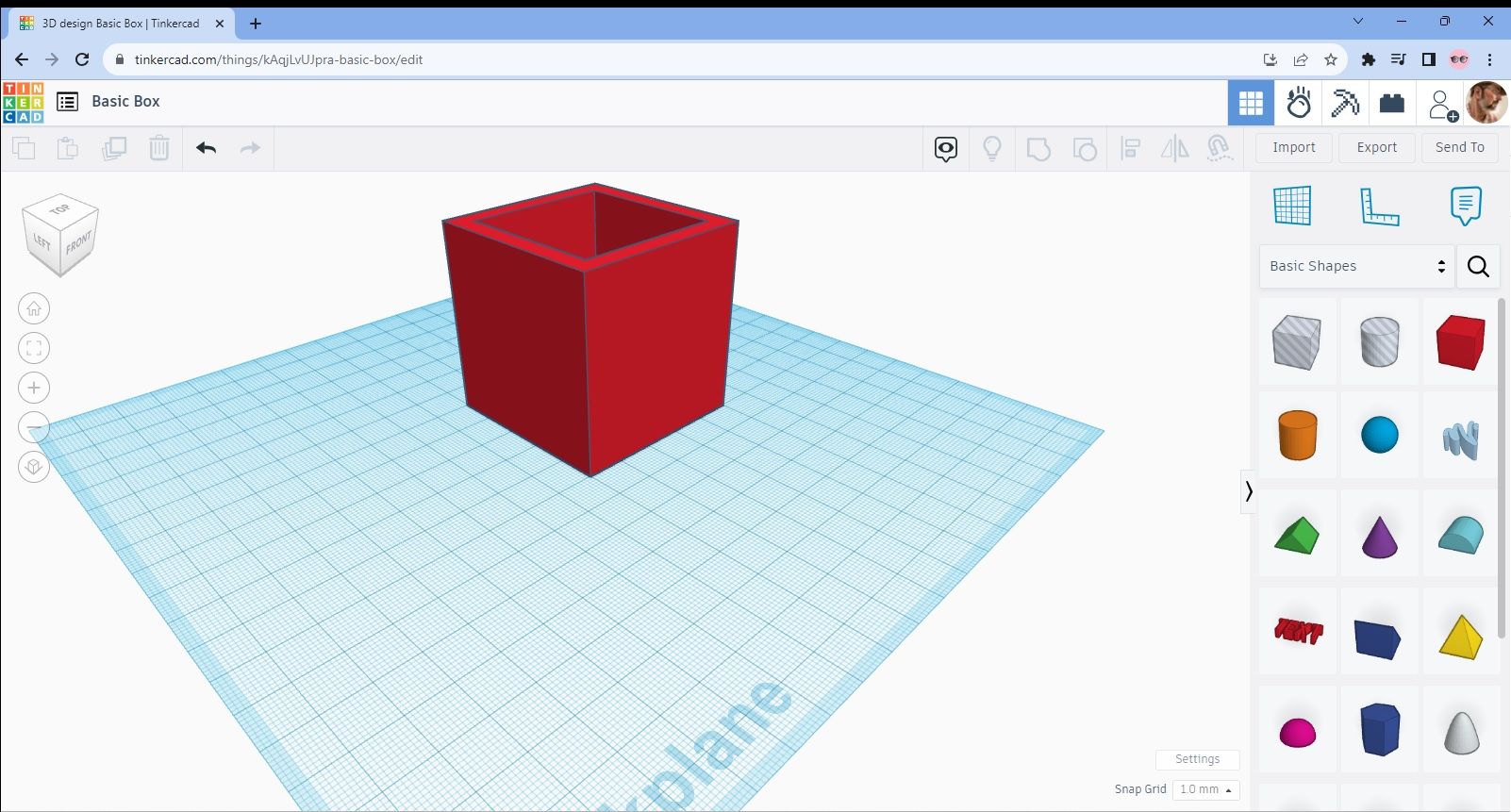
Click on this and you’ll then have your completed box as shown in Image 16.
Image 16
OK, good work. Hopefully you’ve just created your first design in Tinkercad and you should be proud of what you’ve done. However, as I said way back at the start of this, we don’t just want to design a plain little box. So, using the steps I’ve just shown you as a reference, let’s now make something a bit more interesting.
Geeky Inc Keyring Design
That’s right, I think you’re ready for it so let’s see if we can make a Geeky Inc keyring.
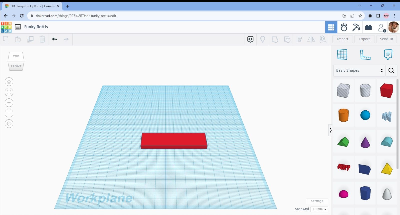
Following the previous steps, you should now be able to get a 20x20x20mm box onto the design area. Once you’ve done that, change the dimensions as we did before but this time to 20x75x5mm and you should end up with a shape the same as in Image A.
Image A
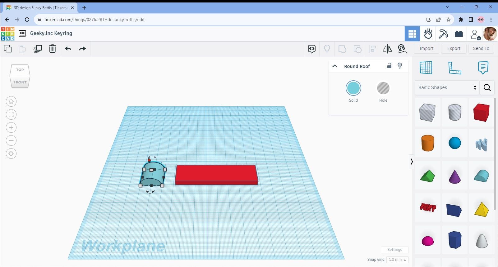
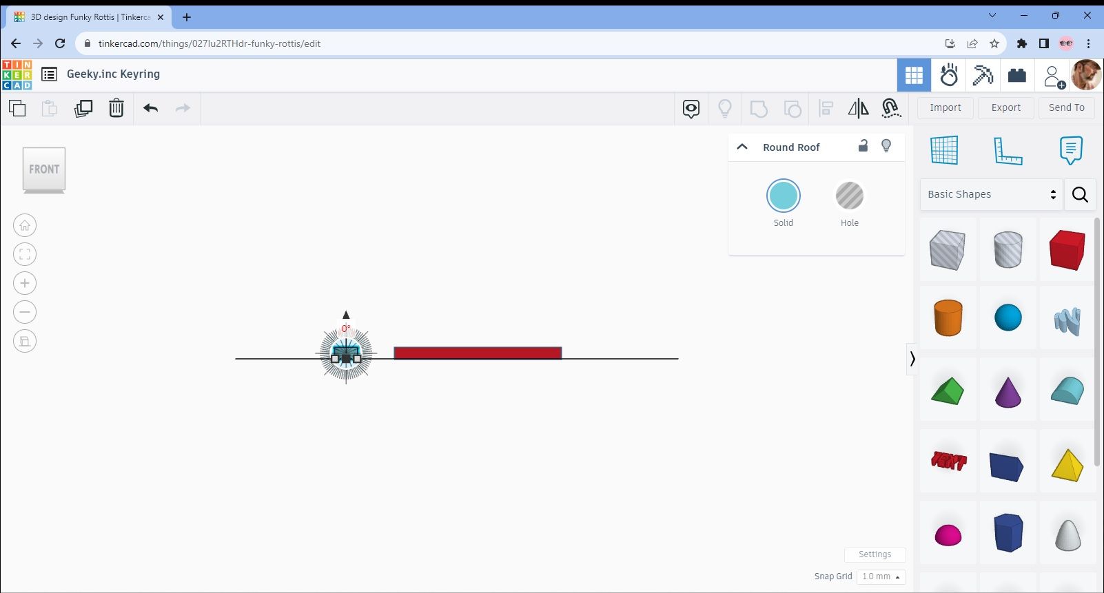
This time though we’re going to add another part to our original rectangle to create a new shape. So, select and drag the “Round Roof” object to the design area and place it near to the rectangle. You’ll now notice though that the new object isn’t really at the right angle as in Image B.
Image B
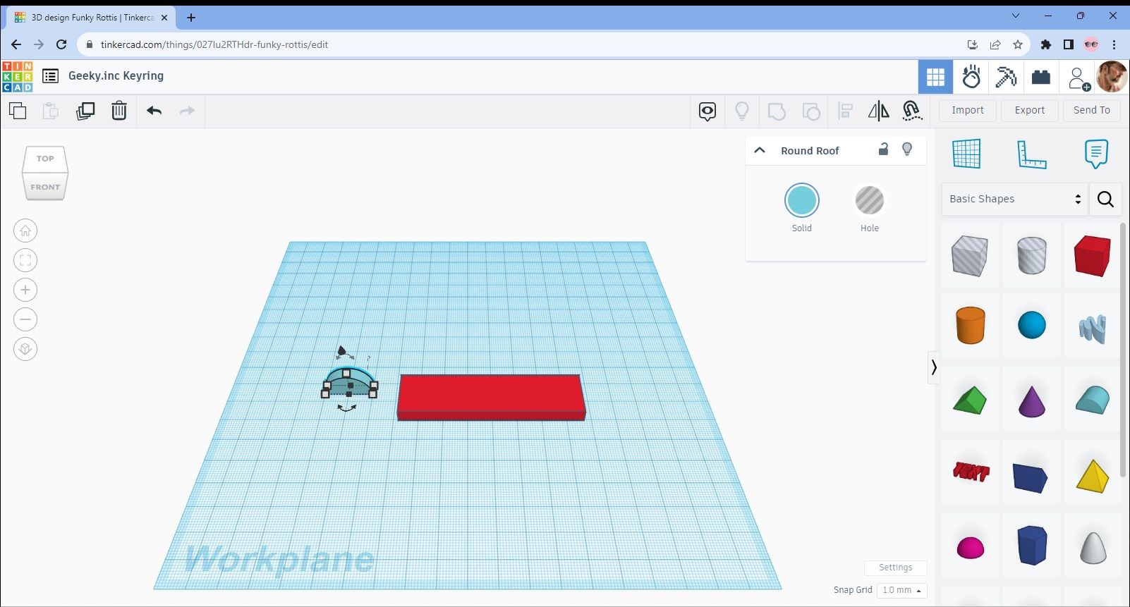
It’s also not the right thickness so let’s fix that first by reducing the length down to 5mm so it matches the thickness of the rectangle. I’ve done this already in Image C in the same way as I did for the rectangle.
Image C
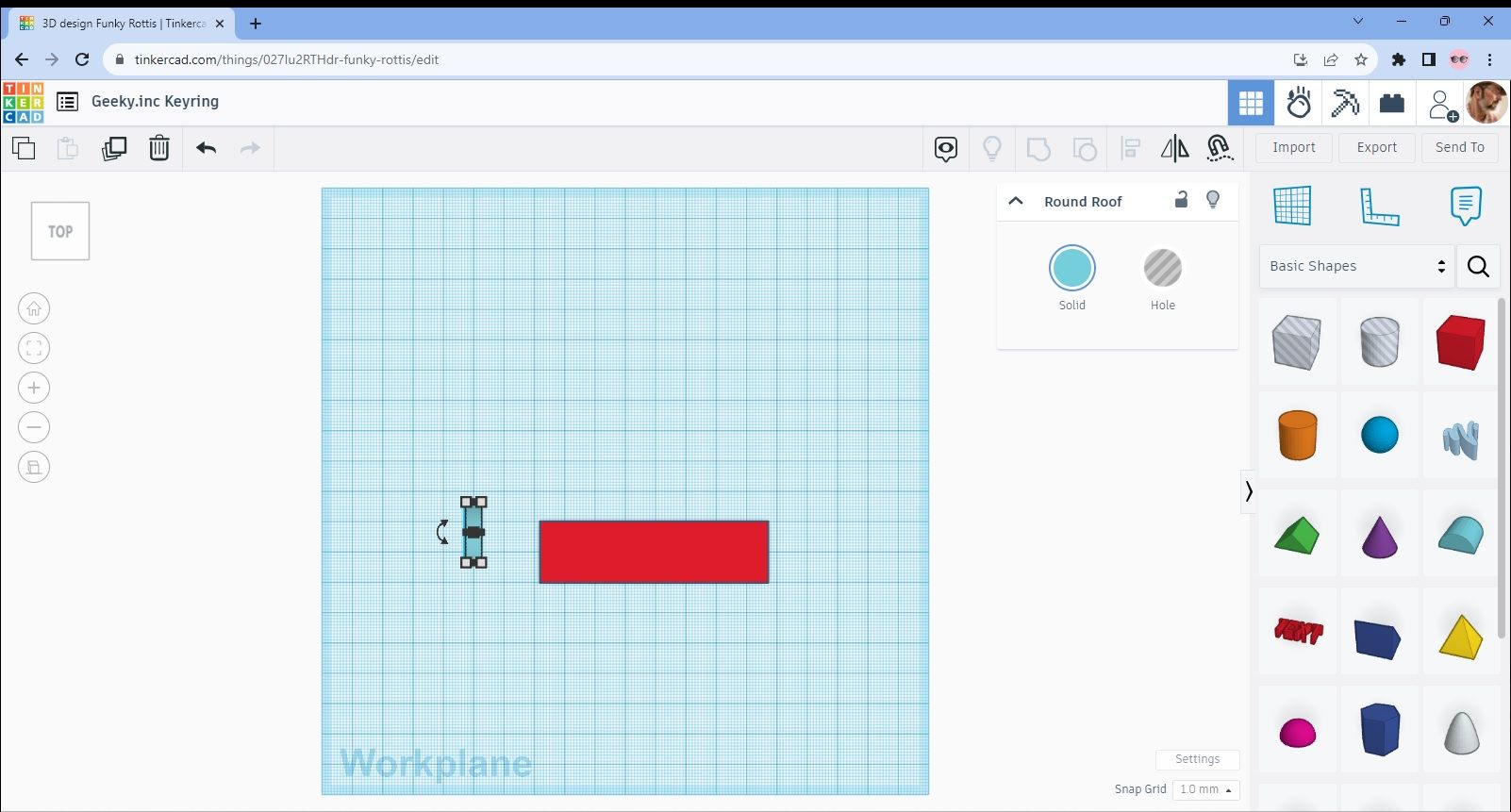
Now it’s time to change the angle by rotating it 90º. You can see the curved arrow in black below the object so you should be able to use that to rotate it. Change the view to 2D for this as its easier and you’ll end up with the object rotated as in Image D.
Image D
We now need to lay it flat so go to the side view (Image E) and then rotate 90º again using the same method as in the last step.
Image E
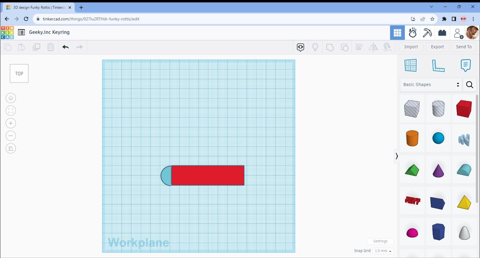
Go back to the top view (Image F) and then move the new semi circular object so that it closely aligns with the end of the rectangle.
Image F
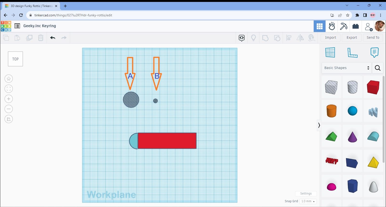
Now we need to make a hole for the ring to go through to make it into a keyring. To do this, select the cylinder shape in the middle top row of the object menu. This is the one that’s “faded” out to grey. Drag it over to the design area and you’ll see that it’s the standard 20x20mm size again. I’ve shown this with arrow A in Image G but we need to reduce it down so it looks like the one indicated by arrow B. Do this in the same way as before but don’t worry too much about the height as this wont matter.
Image G
Move the new “hole” so that it fits neatly into the semi-circle end of the keyring as shown in Image H.
Image H

That’s the basic shape done but its still pretty plain. So, we need to add some text. Go to the shape menu again (Image I) and select and drag the “Text” object to the design area (Image J).
Image I
Image J
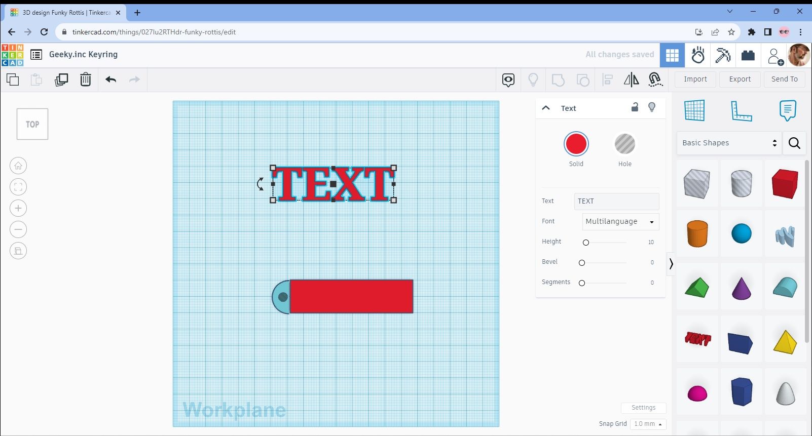
Edit the text so that it reads “Geek Inc” (you can of course put what you want if you prefer) as in Image K.. The text needs to fit neatly into the rectangular part of our design so change the size to 15x65x7mm. The 7mm measurement is important as you’ll see shortly.
Image K
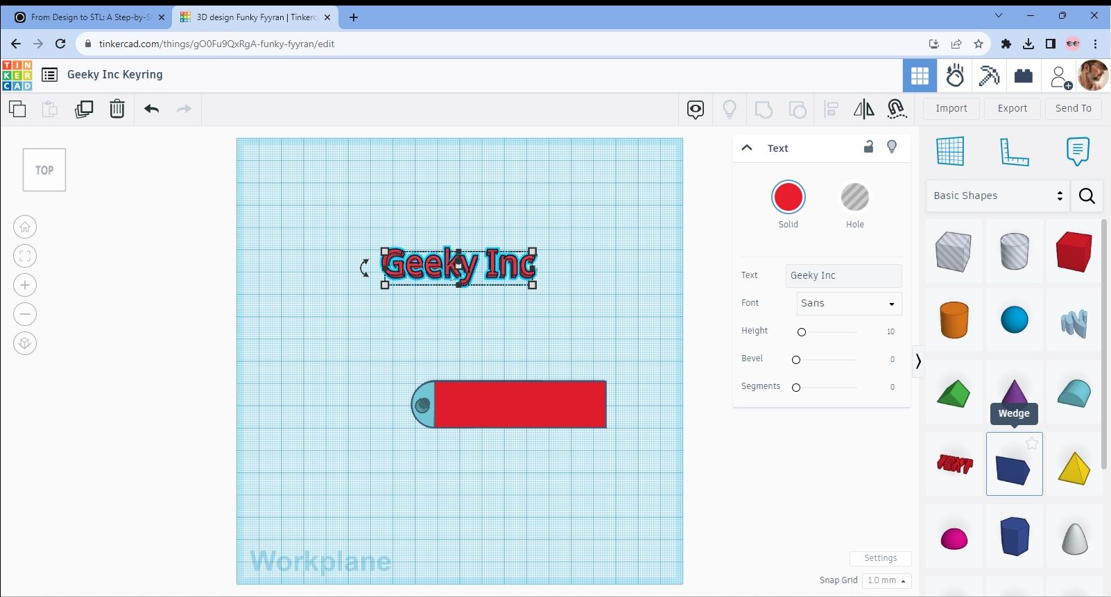
Image L shows the text after I’ve moved it into place on the rectangle. The reason I said to make it 7mm tall should now be apparent as the text is protruding 2mm out from the top of the keyring.
Image L
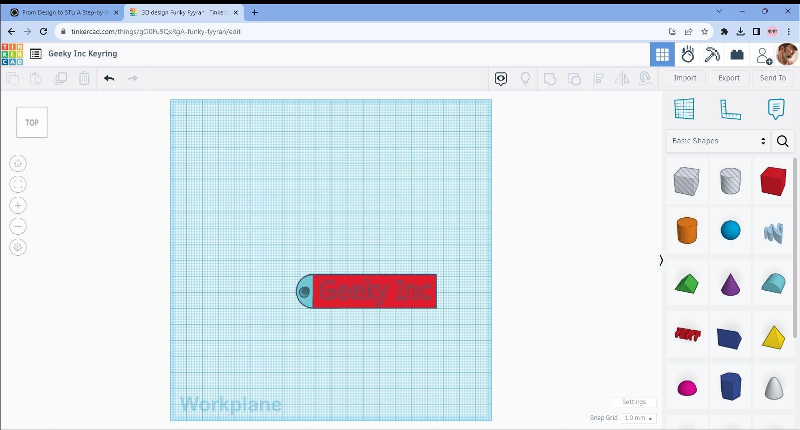
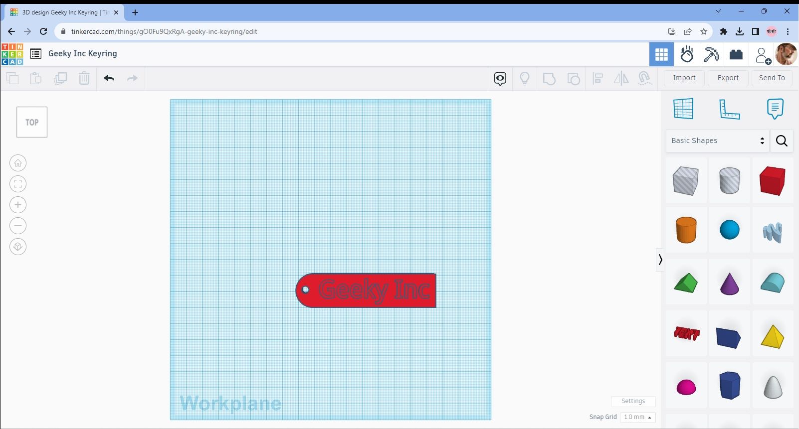
We now need to group all four objects together to make one so do this in the same way as you did for the box and you should then end up with your completed keyring as in Image M.
Image M
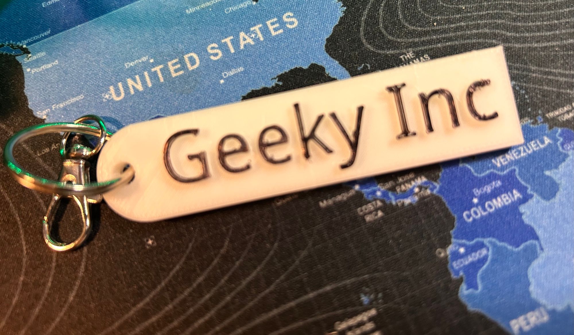
So, there you have it, completed keyring that you just need to add a metal ring to and it’s good to go. I’ve added a further image (N) to show you roughly what your printed item should look like.
Image N

Creating the STL File
I promised you back at the start that I’d show you how to crate an STL file from your design so here we are.
We’ll work with the Geey Inc Keyring design as it was the last one we did and the process is really simple from this stage. Tinkercad automatically saves your work so there’s no concerns about losing the design. The process of converting and saving it as an STL is what we’re ultimately aiming for though and it’s really straightforward.
Click on the “Export” button as indicated by my big orange arrow in Image AA and this will then bring up a menu as shown in Image BB.
Image AA
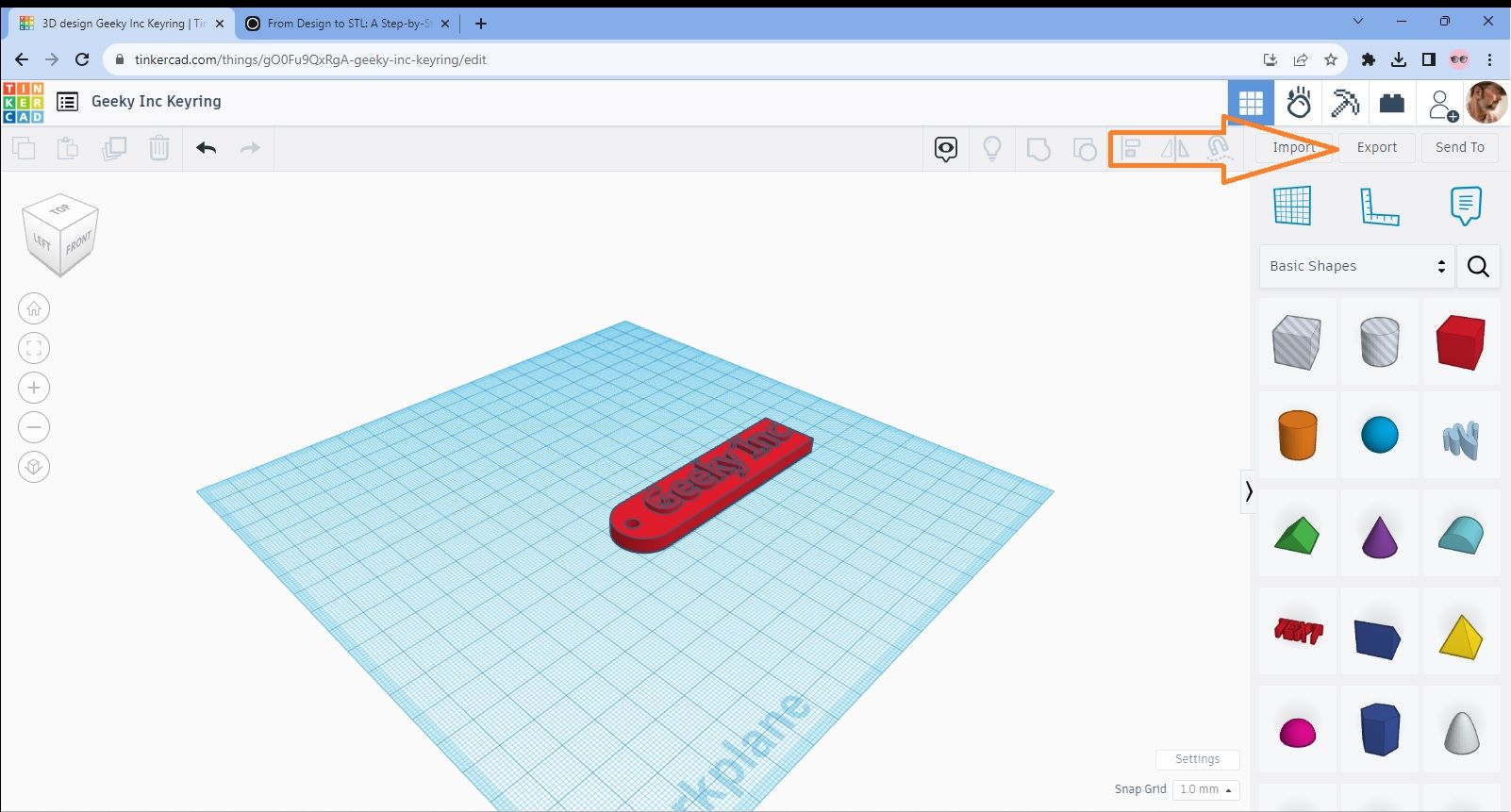
Image BB
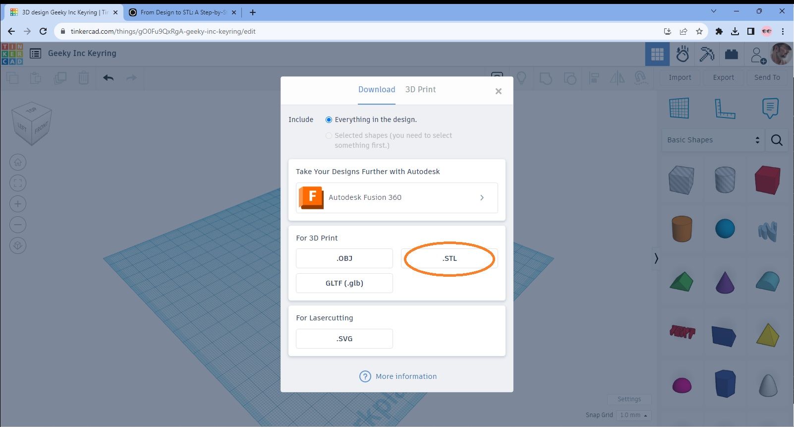
Make sure that you select the option at the top of the menu as “Everything in the design” and then click on the “STL” option as I’ve ringed in the image.
This will then be converted to an STL file and downloaded to your PC. You may want to move it from your “Downloads” file and save it somewhere you can easily locate it later.
And that’s just about it! All you need to do now is use the STL to create your 3D printed model. If you’ve already been printing models that you’ve downloaded from elsewhere then you’ll know what to do next. If not, take a look at my other article “The Beginner's Journey: A Comprehensive Guide to Making Your First 3D Print” which will help.
I actually decided to finish what I'd started and print the keyring. I used a Sharpie to go over the lettering so it stood out more but it looks OK to me. If you consider that once you've got the process of working with Tinkercad under your belt, from desin to finished article took me less than an hour in total. Believe me, it took a lot longer than that to write about it but it was certainly worth the effort! Anyway, here's what it looks like.
The Finished Product!
So, It’s been a fairly long journey but hopefully I’ve given you the building blocks to start out on your own in designing some 3D printable models. I’ve also got you to the stage of knowing how to create STL files for 3d printing.
Have a play around with Tinkercad and certainly check out Blender and Fusion 360 but ultimately just have fun with it and let your creativity take the reins.
Wave 1 — Kitsune Legends Vol. 1
Wave 1 is live.
Four hand-printed fox-spirits. One sealed box. You don't choose your kitsune — you summon it. Limited run, no restock.
Summon your Kitsune on Etsy →


Member discussion