


In this article, I’m going to show you in detail, how you can create a 3d model that will lead to printing success. This will include both how to design 3D print models and how to create a 3D print file.
I’ve looked before at how you can design and print your first 3D model in my articles, “The Beginner's Journey: A Comprehensive Guide to Making Your First 3D Print” and “From Design to STL: A Step-by-Step Guide to Creating 3D Printing Files” . This time though, I’m going to look more deeply into how you can perfect your design and hone your skills using a slicer program to produce the perfect 3D print.
Let’s then begin by looking at taking your designs to the next level.
Designing a Classic
A bit of a play on words there but when we’re all looking to design something original, we’re hoping that it can be the best that it can possibly be. You may well be happy with a basic design but there’s always room for improvement and that aim for perfection.
Previously, I’ve discussed three different 3D design programs, Tinkercad, Blender and Fusion 360. All of these are great and perfectly accessible for both beginners and experts alike. I did say that I would always advise people to start out by using Tinkercad due to its ease of use and sheer simplicity of functionality. If you haven’t read the other articles, I went through how to create a couple of very simple designs and then how to convert them to STL files ready for printing. This is a good start but now
We’re looking to ramp things up a bit and see what can be achieved by maybe using one of the other two programs I mentioned. As I said, these are still very accessible for the beginner but they will challenge your skills that bit further as the range of functionality is itself expanded.
If you create a design and convert it to an STL file in Tinkercad, you may notice that there’s the option to “take your design further with Fusion 360”. This is because both programs are produced by Autodesk with the view that one will lead from the other into advancement of skills and experience.
However, I tend to find that Blender, although it may look more complicated, does in fact give you easier to control editing and gives better results. Therefore, what I want to do here is to take a design previously made with Tinkercad and see if we can enhance it that bit more using Blender.
The Next Step
So, we’ve made our design in Tinkercad and in my case, this was a Geeky Inc keyring. A fairly simple design I’ll admit but functional nonetheless and still requiring some skill to design. Let’s then take Tinkercad’s advice and use Blender to see what else we can do with it.
The first thing of course is to make sure you’ve got the latest version of Blender downloaded and installed on your PC. Once you’ve done this, open it up and you’ll immediately see the difference between this and Tinkercad that you’ve been working with before.
Instead of giving you a design area that resembles the build plate surface of your printer, you’re presented with a 3D “plane” that’s aimed at providing you with an easily accessible 360º view of your design. The UI looks something like this with the design I created in Tinkercad already uploaded:
Image 1
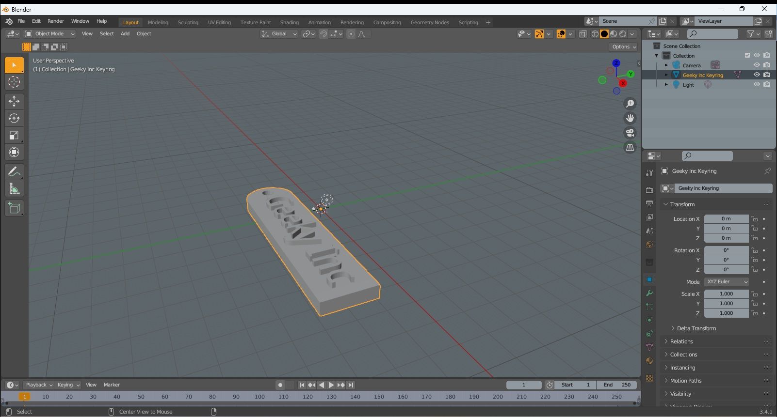
You can already see the difference in the quality and style of Blender as well as the additional tools and features you can use. I won’t go into a fully comprehensive guide to all of the features of the program but I will just show you a few things which may help you enhance the design further,
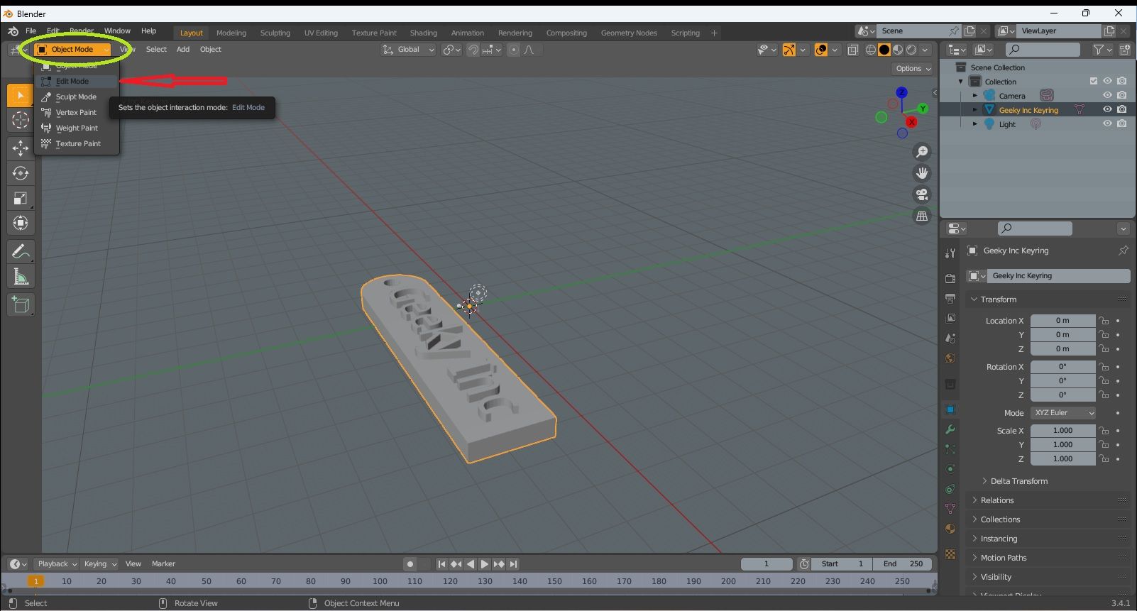
Firstly, the keyring is pretty good as it is and serves its purpose well. I could though maybe round the corners to give it a smoother look. To do this, look at the top tool bar and on the left hand side you’ll see where it says, “object mode”. Click on this and change this to “edit mode” as shown in image 2.
Image 2
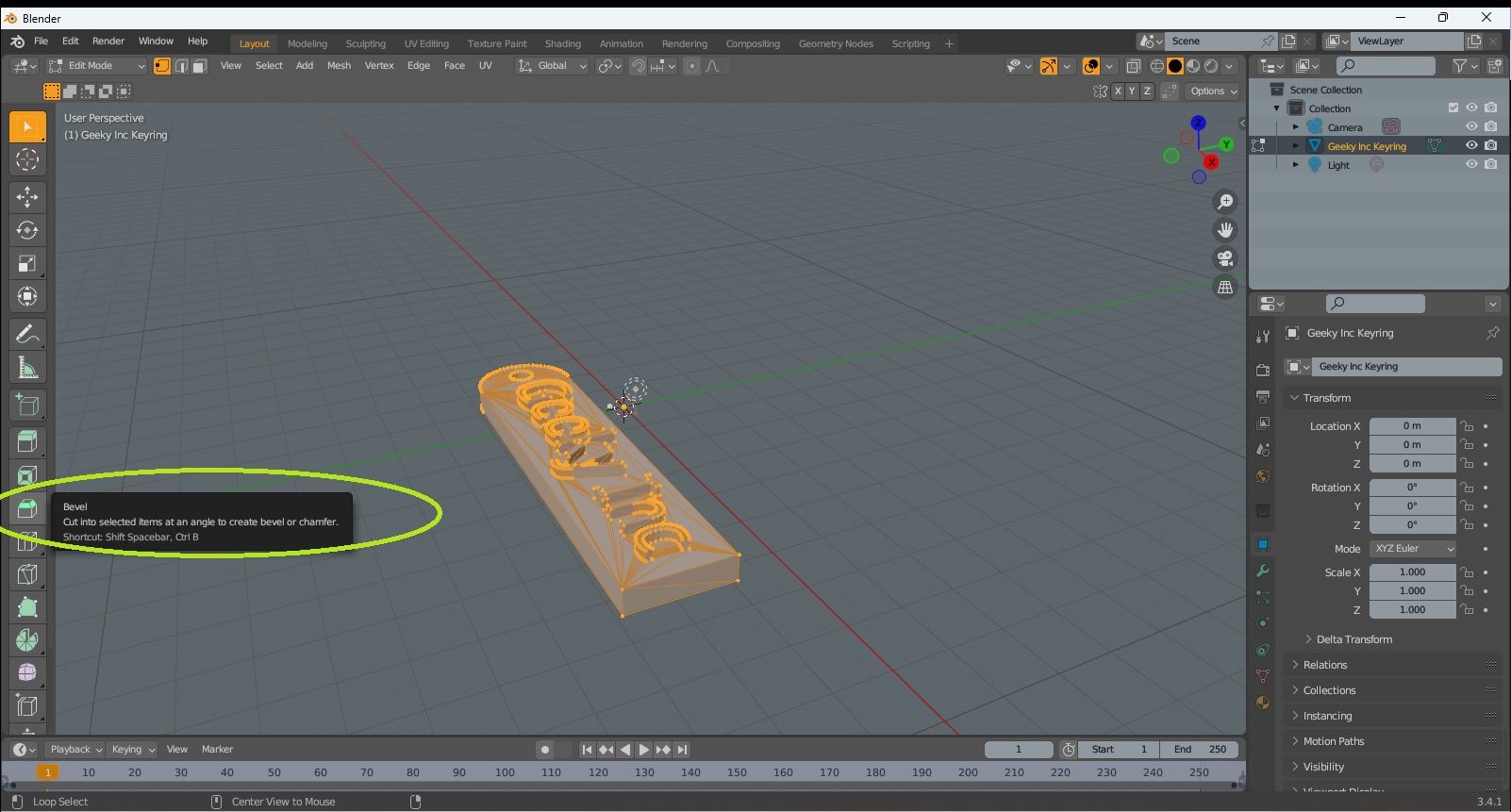
You’ll then see the tool bar down the vertical left hand side of the screen change and give you a lot of editing options. Look down this and you’ll then find the “Bevel” (image 3) tool and we’re going to use this to just take a small bit off the corners of our keyring.
Image 3
Make sure that the object (keyring) is selected and you may want to change view at this point to 2D so you can see all four corners of the bottom end easily. Click on one of the corners and you’ll see a small blue dot appear. Move this slightly and a further menu pops up as shown in image 4.
Image 4
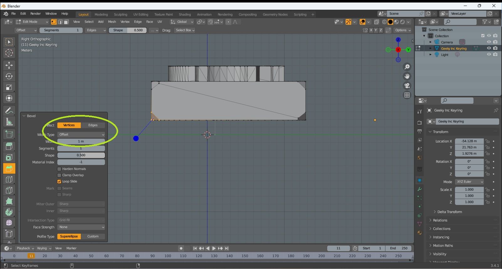
Select “vertices” and then change the figure in the “width” to 1m. This will give a small bevel or chamfer to the corner as you’ll see. Repeat this process for the other three corners and that’s it. You should then have your design looking something similar to image 4.
Remember to both save the file but more importantly, export it as an STL file into an appropriate folder on your PC.
So there you have it. Not much of a change but at least it gives you an idea as to how you can use CAD software such as Blender to enhance your model even a little bit and expand your knowledge of how to design 3D print models. The next thing to do now though is take that design file and see if we can print it to the best possible quality we can.
Slicing
I’ve spoken before in other articles about “slicing” a model and you may of course be fully familiar with the term and how to slice your models. For those of you new to this, or if you just need a refresher, a slicer is a software program that allows you to set certain printing parameters for your 3D design and then convert it to a file format that can be read by your 3D printer.
That’s it in basic terms but how do you go about actually using a slicer to create a 3D print file and which one should you use? Well, we’re specifically looking at FDM printing here so there are a few different slicers that you can use. If you’re looking for an SLA or resin print slicer then try Lychee or ChiTuBox which are both easy to use and will produce great results. For now though, FDM it is so let’s kick off with what is probably the best known and most widely used slicer of them all.
Cura
In the world of FDM 3D printing, probably the most famous slicer is Cura. The people behind this are Dutch company UltiMaker, who started designing, building and selling 3D printers in 2011. They soon realised thought that there wasn’t much in the way of software specifically
for 3D printing so in 2016 they developed Cura, which has probably been used, or at least tried, by most 3D printing enthusiasts at one time or another.
Cura is now basically the benchmark for all other FDM slicers out there and due to its open source format, it has been developed by 3D printer manufacturers into their own bespoke slicing software. We’ll take a look at one of those later but firstly, let’s see what Cura can do for our 3D design.
Again, you obviously need to download and install Cura but its entirely free to use and there are no ads or pop-ups going to interrupt you. Once you’ve done that, open it up and you’ll see the virtual representation of the build area of your printer. Now, I have gone through this stage of things extensively in the other article mentioned at the start so maybe refer to that and then you’ll be at the stage ready to fine tune the design ready for printing.
In the previous article, I showed how to adjust a few of the settings to give a standard quality print but this time we’re going to go a bit more in depth and try and improve the overall quality of our print.
Image 5
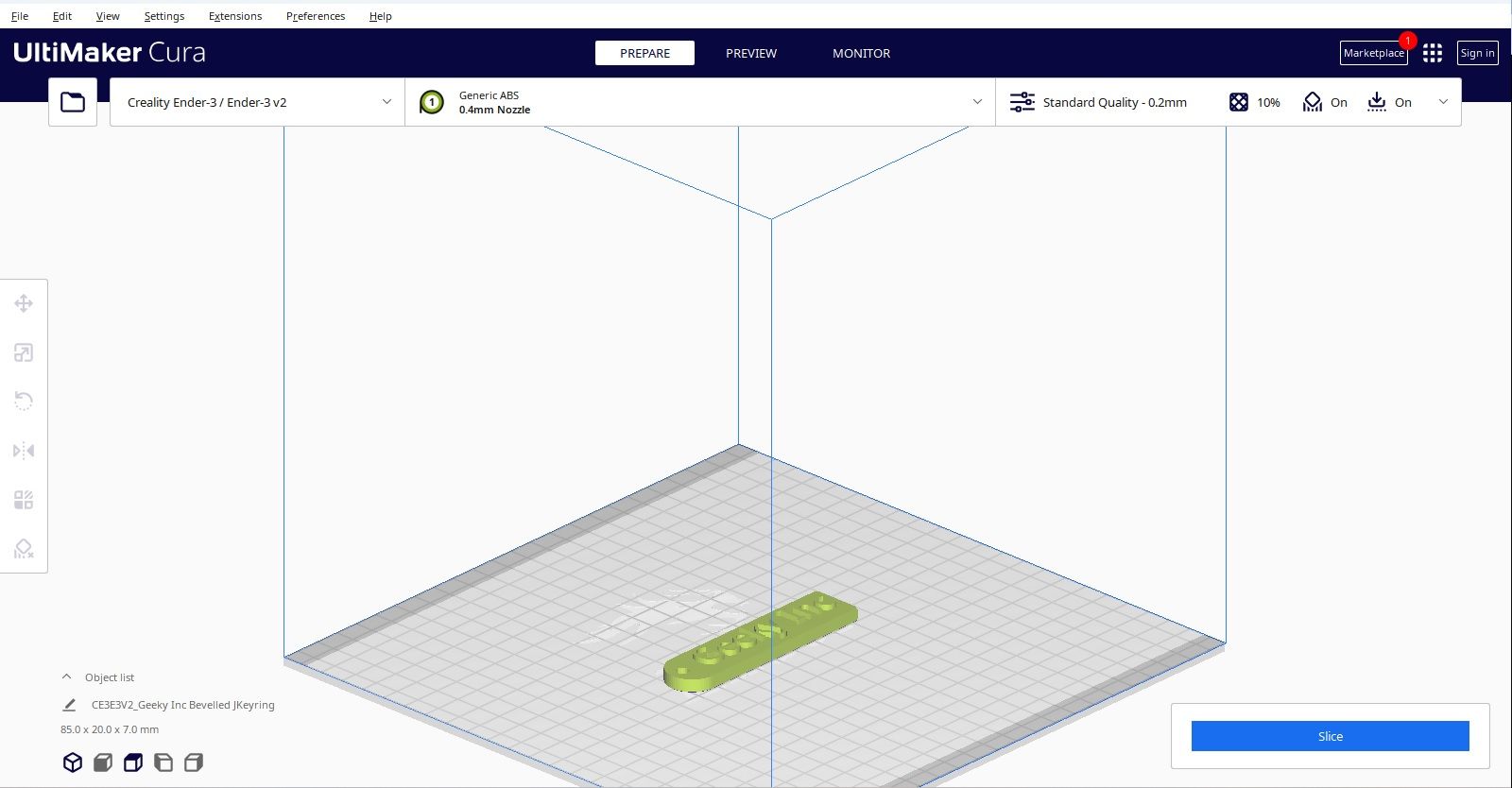
Cura will give recommended setting in the dropdown menu to the right of the screen but I want to change those to improve the quality. The first thing to do then is to go into the “advanced settings” menu which will bring up a long list of settings which can all be adjusted and will all affect the print quality. I won’t add images to show all of the options as we go as that will soon become tiresome. I will though simply go through the most important settings as I descend the list and suggest what to change.
Layer height
This is unsurprisingly the height of each layer of your print. The standard is set at 0.2mm and increasing that will lower the quality so in contrast if I lower it to 0.1mm then it will improve the quality.
Initial layer height
You’d think this should be the same but having a thicker initial layer will improve bed adhesion so I’ll leave that at 0.2mm.
Line width
This relates to how wide each line is deposited onto the print bed and then subsequent layers. It makes sense that , as the nozzle diameter is 0.4mm then leave the line width as the same. Changing this down will give better quality but you’ll also need to change the nozzle size.
The line width setting will also automatically change the rest of the associated settings so we’ll skip those.
Walls
· Wall line thickness: The thicker the wall then the stronger the model will be but it will also greatly increase print time and filament usage. I have though increased this to 2.0mm to give that extra strength
· Wall line count: This will be affected by the wall line thickness and is determined by the line thickness I set earlier. The wall line count in this case is 5 as 2.0mm/0.4mm=5
Infill
Here you can determine the percentage of the infill. For this model it probably doesn’t need more than 10% but obviously increasing this will create a more solid structure. Therefore I’ve changed it to 20% and by doing this you’ll again see that some of the other settings have changed accordingly.
Temperature
The temperature settings will be defined by what type of filament you’re using. This will be different for each type but for this model I’m using PLA.
The recommended temperature for both the nozzle and print bed will probably be shown on the filament packaging but as these don’t vary that much for PLA, I usually stick with 200ºC for the nozzle and 55ºC for the print bed. You can set a different temperature for the start and end of the print but this would only be really necessary if you have build plate adhesion issues.
Speed
The print speed is determined here and usually you might go for a higher speed to get the print done quickly. However, high speeds can affect quality so taking it slow can be better.
The speed you print at will also have an affect on the filament extrusion. Too fast and the extruder might not keep up and you’ll have under extruded gaps in your print. Too slow and clogging and collection of “lumps” on your print layers may be a problem.
A fairly average speed for printing is 50mm/s but for better quality I’ve reduced this slightly down to 40mm/s. You’ll again see that this has changed some of the other settings automatically. These will now probably be half of the print speed you’ve set so in my case, 20mm/s.
The initial layer speed is something that you might want to consider lowering anyway as this will give your print more opportunity to adhere properly to the bed.
Travel
This is when the print nozzle moves across the print while transitioning from one area to another. The speed of this won’t necessarily affect the quality but will change the print time. Having a higher travel speed will also reduce stringing as the filament won’t have time to extrude where not needed.
I’ve set this to 150mm/s already in the speed settings but you’ll also need to enable retraction in the travel settings which will again help with stringing. The retraction setting makes sure that there isn’t continuous extrusion of filament, again where its not needed.
Also make sure to set “avoid supports when travelling” and “avoid print when travelling” for hopefully obvious reasons.
Cooling
You’ll need to set the fans to cool both the nozzle and the printed model so setting these to 100% would be my recommendation for PLA.
We’ll ignore Supports at this stage as this model won’t need any but bear these in mind if printing a model which will definitely need supporting.
Build plate adhesion
This again will depend on the model but in the case of the keyring, it only really needs a brim, if at all, so I’ve set it to that. Other models may need different build plate adhesion settings but this can be down to preference or trial and error experience.
That’s it for now with the Cura settings and I’m sure that what I’ve added will improve the quality of the print over standard.
As I mentioned earlier, there are other slicers that you can use for FDM 3D printing so let’s have a brief look at those to see what’s different.
ideaMaker
The first thing you’ll notice about ideaMaker when you open it is that it looks a bit “slicker” than Cura. That’s not a criticism of the latter but just that some effort has been put into it to make it look a bit different.
The slicer itself is designed to accompany Raise 3D printers in the same way that Cura accompanies Utltimaker printers. However, ideaMaker combines basic aspects of design software with a slicer so could be used quite well if you want to have everything in one place.
Image 6 shows you the UI screen with the model added and you’ll see that the layout is indeed different.
Image 6
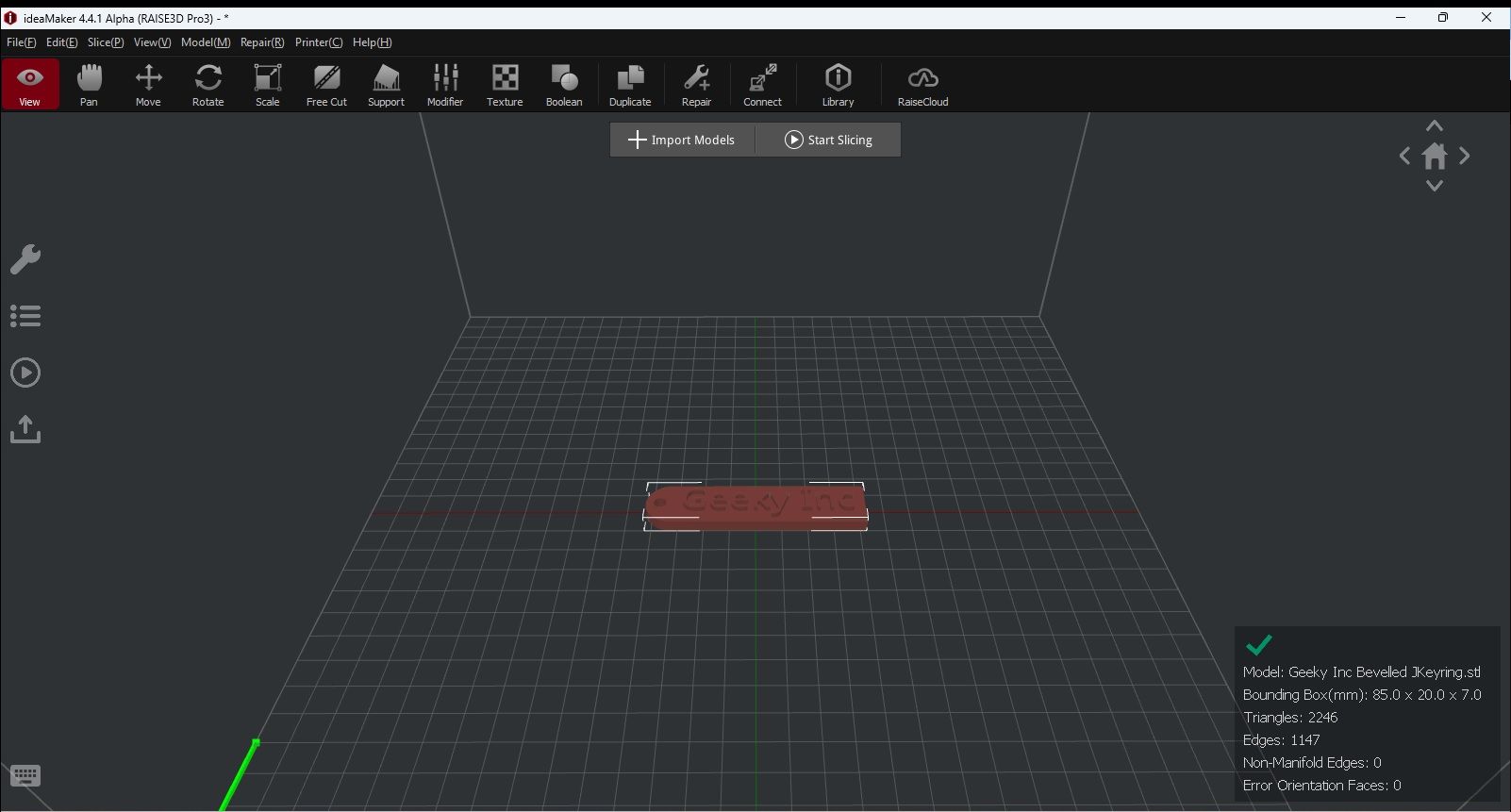
Aside from slicing the model, you can add basic shapes to it much like in Tinkercad and also perform actions like splitting the model into sections. This can be useful in larger models where you may just want to print it in separate parts.
In terms of slicer settings, there aren’t really any settings you can change so it may be a case of using ideaMaker in conjunction with Cura to get the best results.
Creality Print
Creality are the biggest supplier of 3D printers and accessories in the world and have always tried to release their printers with the appropriate software accompaniment. Originally, the slicer of choice for Creality was imaginatively named Creality Slicer and is basically a carbon copy of Cura with all the settings being the same and even the appearance hadn’t really been changed that much.
They therefore decided to up the game slightly and then developed Creality Print which still has Cura as its basis, but with a different look and some added features. Have a look at image 7 and you’ll see the difference but also the similarity to ideaMaker.
This goes down really to the old adage that if it ain’t broke, don’t fix it. Cura pretty much nailed it right off the bat so anything that has come since is always going to try and do things differently, even if change isn’t needed.
Image 7
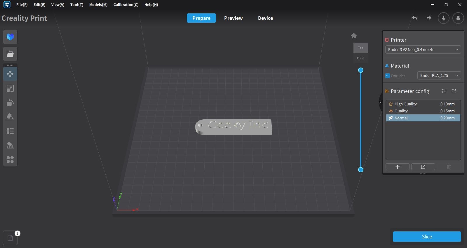
That being said though, Creality Print does bring something to the table in the same way that ideaMaker has. There is a bit more of an option to clone and split models and the settings option is a bit easier and clearer to find.
All the settings that I went through and changed while using Cura are included as presets here so you have the three options of High Quality, Quality and Normal, These all show the layer height as the main parameter change so 0.10, 0.15 and 0.20mm respectively. The presets are all there to make the slicing process a bit easier but can also be edited and added to with your own profiles.
To Conclude…
I’ve gone through briefly what minor design changes you can make by using a more advanced CAD program but I kept it to something really simple to start with. There are of course a multitude of things you could either add or change to any model and once experienced, you’ll leave the basic CAD software behind.
In terms of slicing, there isn’t much that you can do wrong with a slicer once you try it a few times and gain a bit of experience. I’ve gone into a bit more detail with Cura as it is the best in my opinion but there are many other slicers out there including the other two I’ve shown you.
The main thing to remember is that 3D printing should really be a consistent science but each different model may at some point put a spanner in the works with what you might think are the “perfect” settings. But we know that practice makes perfect so keep practicing and you will end up with the perfect 3D print.
Wave 1 — Kitsune Legends Vol. 1
Wave 1 is live.
Four hand-printed fox-spirits. One sealed box. You don't choose your kitsune — you summon it. Limited run, no restock.
Summon your Kitsune on Etsy →


Member discussion